Published as: Ivica Klapan, et. all., Orbit, 2001, 20(1):35-49.
Institutions:
University Polyclinic Klapan Medical Group, Zagreb, Croatia,
Department of Otorhinolaryngology, Head&Neck Surgery, Division of Plastic andReconstructive Head & Neck Surgery and Rhinosinusology, Zagreb University School of Medicine, Zagreb, Croatia
Physics Department, University of Zagreb, Zagreb, Croatia
Department of Radiology, Zagreb University School of Medicine, Zagreb, Croatia
Department of Ophthalmology, Zagreb University School of Medicine, Zagreb
Expert Center for Computer Aided Surgery and Telesurgery of the Ministry of Health, Republic of Croatia
Croatian Medical Association, Croatian Society for Telemedicine, Zagreb, Croatia
Address for correspondence: Professor Ivica Klapan, MD, PhD, University Polyclinic Klapan Medical Group, Ilica 191A, HR-10000 Zagreb, Croatia
Key words: Endoscopy, Retrobulbar foreign body, Three-dimensional visualization, Computer assisted diagnosis, Orbital surgery
This study was in part supported by an unrestricted grant provided by the Ministry of Science and Technology Republic of Croatia (Dr. Klapan)
ABSTRACT
The main goal of our dynamic 3D computer-assisted reconstruction of metallic retrobulbar foreign body following orbital injury with ethmoid bone involvement was to use 3D-information obtained from standard computed tomography data (CT), to explore and evaluate the nasal cavity, ethmoidal sinuses, retrobulbar region, and the foreign body itself by simulated dynamic computerized visualization of the human head. A foreign body, 10x30 mm in size, localized in the cribriform lamina region of the left orbit, was completely visualized. The foreign body partially protruded into the posterior ethmoidal cells, and partially into the orbit, causing dislocation and compression of the muscle rectus medialis and muscle rectus inferior. Other muscles and the optic nerve were intact.
Since 1994, the operability of anatomical regions of the head has been determined by computer, thus making functional endoscopic sinus surgery (FESS) a really computer-assisted three-dimensional operation (3D C-FESS). By connecting surgical instrumentarium to the computer, and operating the computer and multimedial systems during the surgery, this new surgical approach has been completely improved.
Different steps hve been taken in developing diagnostic and surgical activities, e.g., thin CT sections of the nasal cavity, orbit and paranasal sinuses have been performed on a conventional CT device, transmission of CT scans have been done using computer network to different locations, special views very similar to those seen on standard endoscopy have been created; and we also used special software for 3D modeling, partially created and modified by ourselves for 3D C-FESS purposes, as well as connection of the 3D-digitizer to the computer, and multimedia navigation through the computer during 3D C-FESS.
The visualization of the relationships of very delicate anatomical structures within the orbit in unconventional (non-standard) section and angles of viewing, impossible to perform by standard endoscopy or 2D-CT scanning, both on surgical planning and during the surgery, points to a number of advantages of our approach. Finally, virtual endoscopy (VE) or 'computerized journey' through the anatomical spaces of paranasal sinuses and orbit has substantially modified the type of operation according to the requirements of the 3D C-FESS diagnostic procedure.
Similar surgical procedures of the nose and paranasal sinuses, introduced by our are shown on the Web site of our 3D C-FES surgical team at www.mef.hr/MODERNRHINOLOGY
INTRODUCTION
The main purpose of our three-dimensional computer assisted functional endoscopic sinus surgery (3D C-FESS) technique is to define the 3D-computer assisted support in standard functional endoscopic sinus surgery (FESS)1, and to develop a safer surgical procedure by producing a real and advanced visualization of the anatomy and pathology, using a completely new computer and medical technologies2-4. Such an approach should allow a considerably better insight into the operating field, and a significantly greater safety of the procedure.
This very approach appeared ideal for use in both the diagnosis and surgical treatment of penetrating injury of the orbit and posterior ethmoidal cells of the paranasal sinuses, inflicted by a metallic foreign body.
As a number of parameters necessary for a satisfactory outcome of the operation could not be positively determined by standard preoperative surgical planning, we embarked upon examination of the anatomical region of the nose, paranasal sinuses and orbit by use of the 3D C-FESS technique criteria. The use of this new technique in the surgery of paranasal sinuses and adjacent anatomical regions proved advantageous in the present case as well, as the retrobulbar foreign body could not be removed by the standard, 'classical' endoscopic and surgical technique, not even with the use of 2D-CT sections of the region.
The region of paranasal sinuses and surrounding structures, i.e. orbital and skull base area, have a very complex anatomical architectonic, because a large number of different anatomical structures are located within a relatively small space. Beside history and status data, computed tomography (CT) is a crucial method in diagnosing the pathology in the mentioned regions5.
However, standard stratified CT image suffers from some shortcomings but nowadays, attempts have been made to overcome these drawbacks by computer processing of two dimensional (2D)-CT sections. It was necessary to develop a new, third dimension (3D) approach in both preoperative and intraoperative head imaging, which will provide a completely new insight in any surgical procedure6.
Owing to the advances in computer technology, computers capable of creating 3D models of the observed region from stratified digital images within a short period of time employing various methods of digital image processing, have become available.
MATERIALS AND METHODS
a) Case report
A 28-year-old healthy man, suffered a penetrating injury in the region of the left palpebral fissure while working on a metal object, which caused a 3-mm laceration of the eyelid edge and eyeball penetration involving entire cornea diameter and continuing into the orbit by 4 mm. The foreign body was almost completely retained in the orbit, with a minor segment protruding to the region of posterior ethmoid sinus cells.
The patient was conscious on admission to the Department of Ophthalmology, 3Zagreb University Hospital Center, where the necessary examinations were performed.
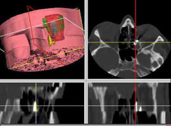
Orbit x-ray indicated a foreign body, showing a shadow intensity characteristic of a metal object in the region of medial and posterior segments of the orbit, with suspected fracture of the base of the orbit. CT scanning of the orbit revealed a foreign body, 10x30 mm in size, in the cribriform lamina region of the left orbit, which partially protruded into the posterior ethmoidal cells, and partially into the orbit, causing dislocation and compresson of the muscle rectus medialis and muscle rectus inferior (Fig. 1).
Figure 1. CT of the orbit and paranasal sinuses
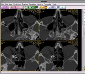
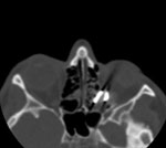
Other muscles and the optic nerve were intact. Pronounced chronic inflammatory changes with signs of ostiomeatal block were observed in the region of ethmoidal cells and left maxillary sinus (Fig. 2).
Figure 2. CT image of the metallic foreign body on axial, coronal and computer-generated sagittal CT section
The eyeball was filled with blood, however, with maintained tonus and sutures in the region of the upper eyelid, cornea, conjunctiva and orbit. Visual function was reduced to uncertain light perception. A normal finding was recorded on the right eye. Vitrectomy, and suturing of the cornea and sclera were performed. Postoperatively, antibiotic therapy with local corticosteroids and mydriasis was prescribed.
b) CT scanning
Standard CT scans in coronal and transverse sections of 3-mm thickness were performed on a Sytec 2000+ (General Electric). Five-mm transverse CT sections were performed in a plane parallel with the hard palate and the patient in supine position, whereas 3-mm coronal CT sections were performed in a plane perpendicular to the hard palate with the patient in prone position with neck hyperextension.
These CT images were used to design the static and dynamic 3D models of paranasal sinuses. Two-dimensional coronal and transverse sections were compared with 3D models. The static and dynamic 3D models and VE of the sinuses were used in surgerical planning and were available to the surgeon in the operating room throughout the procedure. All CT images obtained were stored on film and in digital form on a magnetic medium (hard disk).
Hardware used in 3D C-FESS:
IMAGE DISPLAY: SGI-O2 Workstation, Color 20’ monitor, 1280x1024x75Hz, 232 colors, double buffered (32+32-bit)
COMPUTER:SGI-O2, 128 MB system RAM, CD, 4GB system disk, IRIX 6.3
operating system, 33600 Baud Modem, Fast Ethernet,
PROCESSING POWER: 4.6 SPEC int 95, 5.4 SPEC fp 95
USER INTERFACE: Mechanical mouse, Keyboard, X-wind./MOTIF/Indigo magic
CT or MRI INPUT : Ethernet using DICOM Standard
OTHER: NTSC/PAL S-video output, HP 1100 A Laser Printer.
Endoscopes, standard FESS-instruments, cold-light sources, monitors, endo-micro camera, video recorder.
Softwares used in 3D C-FESS:
3D Viewnix V1.1 - http://www.mipg.upenn.edu7
Analyze AVW - http://www.mayo.edu/bir
T-Vox V1.0 - http://www.ht.com
Elscint OmniPro 2.2 - http://www.elscint.co.il
SGI Showcase V3.4.1 - http://www.sgi.com
Starvision StarMED - http://www.starvision.com
DISCUSSION
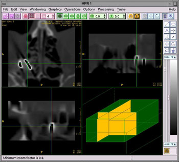
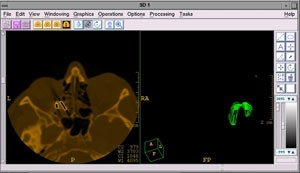
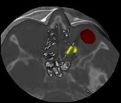
In our patient, the presence of a foreign body in the medial and posterior region of the orbit, with suspected fracture of the base of the region, was diagnosed with plain x-rays. As it was a high-density metallic foreign body, the basic diagnosis was quite easy to make, however, highly reflective structures such as bone tissue posed certain difficulties, especially in the borderline area toward the region of posterior ethmoidal cells6.8. The high-density foreign material in the orbit was detected with a high level of certainty by use of CT sections9 of the orbit and paranasal sinuses in axial and coronal sections. It was tin fragment, 10x30 mm in size, so only its approximate location and possible contact with the vital anatomical structures within the orbit could be definitely determined. Although it is known that a metallic foreign body of not more than 0.3 mm in size within the orbital region could be visualized by CT scanning3,10, in our case this approach proved efficient only for the diagnostic purpose of foreign body localization and its identification within the retrobulbar area. Basic contours of the foreign body and the structures surrounding the orbit could not be visualized with certainty, neither was it possible to determine whether there actually were two disparate, mutually connected fragments of the foreign body, or a single, irregularly bent tin fragment, or two foreign bodies close to one another. (Fig. 3. a, b, c, d).
Figure 3 a, b, c, d. 3D and 2D-CT views of the metallic retrobulbar foreign body
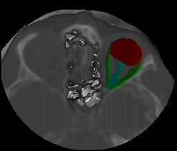
The main reason for insisting on precise determination of the shape, position, and number of foreign bodies was the unfavorable location of the foreign body. With its proximal part, the foreign body was in tight contact with the dislocated and compressed muscle rectus medialis and muscle rectus inferior. Other muscles and the optic nerve were intact, however, the distal, bent edge of the foreign body was very close to the optic nerve (Fig. 4). Figure 4. 2D and 3D views of the metallic foreign body
Therefore, this main diagnostic problem could not be solved by the use of either plain x-rays or CT sections, which considerably hampered the process of preoperative planning.
Visualization of the region by the magnetic resonance imaging (MRI) would not be permitted in this case because the patient had metallic material inside the orbit11.
Foreign bodies lying along the medial wall of the orbit are known to be quite difficult to visualize and to remove by the 'lateral' approach, while the approach through medial conjunctiva is quite questionable and limited12. Thus, the approach combining medial and lateral orbitotomy may be tried in such cases. The approach with disinsertion of the muscle rectus medialis, with temporary dislocation of the eyeball, provides quite a good view of the region of the orbital medial apex. However, this approach has proved satisfactory only in case of small foreign bodies of a relatively flat surface, because large foreign bodies could significantly derange anatomical relations in the region. The medial wall of the orbit is very delicate and susceptible to fracture or inflammatory changes induced by even a very low force. In our case, the suspected fracture of the base of the orbit required due consideration on choosing surgical approach to the region.
The golden rule usually applied on removing large foreign bodies of the region says that these foreign bodies should be removed in a direction parallel to the axis of the entry wound, avoiding twisting or prying motions12. Unfortunately, the rule could not be used in our case, because the foreign body was sharp and markedly bent and dentated on both sides. The eyeball and its bone structures that cannot be moved posed an additional problem.
Therefore, the percutaneous surgical approach by a modification of Lynch incision appeared to be the most favorable mode of treatment. The medial transconjunctival approach may have also provided limited visualization of the foreign body and of the borderline area of the orbit and posterior ethmoids, however, with a highly probable hemorrhage due to periosteal lesion and nasolacrimal draining system impairment.
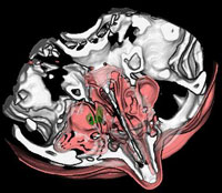
A question to which no definite answer could be reached was whether an additional lesion to the muscle rectus medialis and muscle rectus inferior had occurred upon the foreign body extirpation by FESS, through the borderline area of the posterior ethmoids where a foreign body edge was discerned. Neither was it possible to determine whether this standard endoscopic approach by uncontrolled 'rightward' or 'lefward' manipulation on foreign body extirpation would have caused additional lesions to the muscular structure or the optic nerve itself (Fig. 5 a, b, c, d).
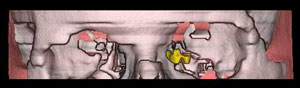
Figure 5 a, b, c, d. Different 3D models with evidence of the metallic foreign body in correlation with other anatomical structures


As 3D C-FESS operations imply a surgical approach per viam standard FESS with a computerized 3D support, an operative approach to the foreign body through the lateral wall of posterior ethomoids, and through the medial wall of the orbit (lamina papiracea) had to be planned. The latter wall had already suffered massive destruction by the penetrating force of the projectile. An additional problem was the periorbital fatty tissue which partially filled the posterior ethmoid labyrinth, thus considerably hampering the foreign body localization and removal.
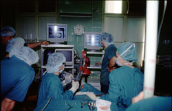
Considering all the facts mentioned above, we decided to remove the foreign body by use of 3D C-FESS (Fig. 6), because we considered it to be the safest procedure for the patient. We have generally followed this principle on many surgical procedures of the nose and paranasal sinuses carried out at our ENT Department13.
Figure 6. Our 3D C-FESS equipment

The 3D C-FESS procedure performed by use of a 3D-digitizer (Immersion) was based on the following main principles of the technique: a) design of the static and interactive dynamic 3D models of paranasal sinuses and adjacent anatomical structures per viam special computer programs; b) using rotation and changing observation point, separation and segmentation of various structures, and visualization of various structures in different colors; c) defining the degree of particular structure transparency, exclusion of particular structure visualization from the model, and model magnification and diminution; d) animation of 2D-CT sections of the nose and paranasal sinuses with comparison of standard 2D-CT sections of paranasal sinuses with 3D models of the same region; and e) VE technique14 was performed when the computer simulation of the endoscopic procedure had been done.
Considering the extremely complex anatomical structure of the orbit and paranasal sinuses as well as the need of a precise diagnosis for 3D C-FESS-planning, the basic aim of our 3D C-FESS approach also was to evaluate the reliability of the known 3D static model in the diagnosis of the pathology in the paranasal sinuses, as well as to test it on a dynamic 3D model and VE, which has to be done by using the possibilities offered by the sophisticated computer technology. This final step in the diagnostic procedure yielded additional preoperative information which was of great importance in surgery planning, because we “simulated” the route of the endoscope preoperatively, whereafter images were generated by the computer. Using the “live” video image mapping on the anatomical region 3D models provides not only better survey of the procedure, but overlying of the respective region onto the volume rendered model with video image we are able to create various complex anatomical structures of the orbit and paranasal sinuses, which would provide a highly precise diagnosis as well as the most sophisticated quidance through the operation itself15. Finally, it could also be used as a basic technique in tele-computer assisted surgical activities, as our team has already done16.
So, when we used static 3D models, elaborated from 2D CT sinus section, we obtained relative relationships of the borderline areas that are important for the diagnosis of pathologic conditions in the region, and a significant improvement in comparison with 2D visualization in the form of stratified images (Fig. 7 a, b).
Figure 7 a, b. Static 3D models of the orbit and paranasal sinuses
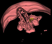
With the use of computer techniques of segmentation and presentation of various tissues with different colors as dynamic 3D models ,we allowed visualization of various anatomical structures in real time as well as of their spatial interactive relationships from all aspects possible. We believe that a 3D model of paranasal sinuses could be designed within 30 minutes, depending on the pathologic condition complexity and quality of the hardware and software available.
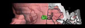
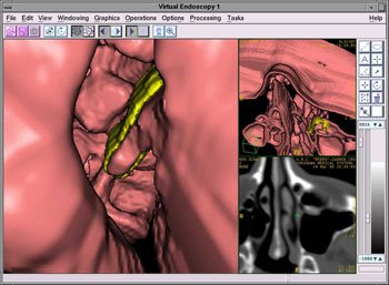
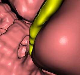
Finally, using the technique of VE, we simulated the endoscope tip penetration through the orbit, nose and paranasal sinuses which cannot be explored by the existing endoscopic methods, i.e. using only the FESS approach. (Fig. 8 a, b).
Figure 8 a, b. Virtual endoscopy through the region of paranasal sinuses
During the 3D C-FESS operation, our main concern was to prevent any additional damage to the muscle rectus medialis, muscle rectus inferior and optic nerve on foreign body removal. As the proximal part of the double-bent tin fragment leaned against the muscle rectus medialis, encircling it by its anterior bent edge along the medial wall of the orbit in parallel with the other bent edge, the act of extirpation had to be carried out in such a way as to slightly rotate the foreign body on its axis and drag it through the region of posterior ethmoids to the nasal region (Fig. 9 a, b, c).
Figure 9 a, b, c. Computer aided surgery: foreign body removal per viam 3D C-FESS
Close contact of the distal part of the foreign body with the optic nerve posed an additional problem. On rotating, utmost care was taken not to move the distal part of the foreign body even by a millimeter, to prevent damage to the optic nerve.
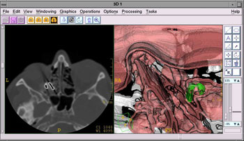
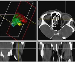
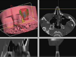
By use of the 3D C-FESS technique, the foreign body was removed in no more than 10 minutes. All the rules described were strictly followed during the procedure. No additional lesions to the muscle rectus medialis or optic nerve that may have been induced by various instrumentarium manipulations during the 3D C-FESS procedure were observed (Fig. 10 a, b).
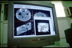
Figure 10 a, b. 3D C-FES-operation. Visualization of the paranasal sinuses and surrounding regions from different aspects (coronal, axial, sagittal and 3D)
Upon completion of the operation, our presumption on a metallic foreign body, sharply bent on both ends and bent in its middle part was confirmed (Figs. 11, 12).
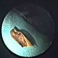
Figure 11. 3D C-FESS: live video image through the endoscope with the “first sign” of the metallic foreign body in the left posterior ethmoidal cells.
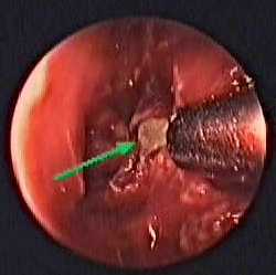
Figure 12. The curved metallic foreign body after 3D C-FESS extraction.
During the postoperative course, atrophy of the eyeball developed. As the eye was without stimuli, a laminar prosthesis was used, and has since been well tolerated by the patient.
REFERENCES:
1. Klapan I, Šimičić Lj. The main difference between FESS and 3D C-FESS 1998; HMA, 22 (Suppl. 2): 52.
2. Roth M, Lanza DC, Zinreich J, Yousem D, Scanlan KA, Kennedy DW. Advantages and disadvantages of three-dimensional computed tomography intraoperative localisation for functional endoscopic sinus surgery. Laryngoscope 1995; 105: 1279-1286.
3. Anon JB, Lipman SP, Oppenheim D, Halt RA. Computer-assisted endoscopic sinus surgery, Laryngoscope 1994; 104: 901-905.
4. Klapan I, Šimičić Lj, Udupa JK. Three-dimensional computer assisted functional endoscopic sinus surgery. Pre-operative planning and intraoperative guidance. Comput Med Imaging Graph, 1999 (submitted).
5. Lakits A, Steiner E, Scholda C, Kontrus M. Evaluation of intraocular foreign bodies by spiral computed tomography and multiplanar reconstruction. Ophtalmology 1998; 105 (2): 307-312.
6. Hesse L, Volk JN, Wiegand W. Computer-assisted, improved evaluation of Comberg images with three-dimensional graphic reconstruction. Klin Monatsbl Augenheilkd 1994; 204 (4): 248-251.
7. Udupa J, Hung H, Odhner D, Goncalves R. 3DVIEWNIX: a machine-, data- and application-independent software environment for the visualisation and analysis of biomedical structures. J Scanning Microsc 1991; 13: 132-133.
8. Rahman NU, Jamjoom A, Jamjoom ZA, Abu el-Asrar A. Orbito-cranial injury caused by penetrating metallic foreign bodies: report of two cases. Int Ophtalmol 1997; 21 (1): 13-17.
9. Espaillat A, Enzer Y, Lipsky S. Intraorbital metallic foreign body. Arch ophtalmol 1998. 116 (6): 824-825.
10. Guthoff R, Hagemann J, Heller M. Possibilities of locating foreign bodies by computed tomography. Graefes Arch Clin Exp Ophthalmol 1982; 218: 307-310.
11. Williamson MR, Espinoza MC, Boutin RD, Orrison WW Jr, Hart BL, Kelsey CA. Metallic foreign bodies in the orbits of patients undergoing MR imaging: prevalence and value of radiography and CT before MR. AJR Am J Roentgenol 1994; 162 (4): 981-983.
12. Karciogly ZA, Nasr AM. Diagnosis and management of orbital inflammation and infections secondary to foreign bodies: a clinical review. Orbit 1988; 17: 247-269.
13. Klapan I, Šimičić Lj, Kubat M, Rišavi R. Fracture of the ethmoid and medial orbital wall. Removal of the bullet per viam 3D C-FESS. In: Ribari O, Hirschberg A (eds): 3rd EUFOS. Bologna, Monduzzi Editore Int. Proc. Division, 1996; (Vol. II): 83-87.
14. Robb RA. Virtual (computer) endoscopy: development and evaluation using the visible human datasets. National Library of Medicine, NIH, Bethesda, Mayo Foundation Clinic 1996; 1-32.
15. Šimičić Lj, Klapan I, Simović S, Brzović Z, Vukoja M, Rišavi R, Gortan D. Computer assisted functional endoscopic sinus surgery. Video texture mapping of 3D models. In: Stammberger H, Wolf G (eds.): E.R.S. and I.S.I.A.N, Vienna, Austria, Bologna, Monduzzi Editore Int. Proc. Division 1998; (Vol. II): 281-285.
16. Klapan I, Rišavi R, Šimičić Lj, Simović S. Tele-3D C-FESS approach with high-quality video transmission. Otolaryngol Head Neck Surg 1999.